Jude 1:3

The sin and doom of Godless men
3Dear friends, although I was very eager to write to you about the salvation we share, I felt I had to write and urge you to contend for the faith that was once for all entrusted to the saints.

Comments:
All of us intend to worship God.Many who disobey the words of God ,many who criticize but all we must do is follow the bible words for our salvation.Saint jude urge us to have faith in God.All we need is love of God and the words of God.

Tuesday, January 19, 2010

T1(T CARRIER)


In telecommunications, T-carrier, sometimes abbreviated as T-CXR, is the generic designator for any of several digitally multiplexed telecommunications carrier systems originally developed by Bell Labs and used in North America, Japan, and Korea.

The basic unit of the T-carrier system is the DS0, which has a transmission rate of 64 kbit/s, and is commonly used for one voice circuit.

The E-carrier system, where 'E' stands for European, is incompatible with the T-carrier (though cross compliant cards exist) and is used in most locations outside of North America, Japan, and Korea. It typically uses the E1 line rate and the E3 line rate. The E2 line rate is less commonly used. See the table below for bit rate comparisons.

The most common legacy of this system is the line rate speeds. "T1" now means any data circuit that runs at the original 1.544 Mbit/s line rate. Originally the T1 format carried 24 pulse-code modulated, time-division multiplexed speech signals each encoded in 64 kbit/s streams, leaving 8 kbit/s of framing information which facilitates the synchronization and demultiplexing at the receiver. T2 and T3 circuit channels carry multiple T1 channels multiplexed, resulting in transmission rates of 6.312 and 44.736 Mbit/s, respectively.

E1(E CARRIER)

In digital telecommunications, where a single physical wire pair can be used to carry many simultaneous voice conversations, worldwide standards have been created and deployed. The European Conference of Postal and Telecommunications Administrations (CEPT) originally standardized the E-carrier system, which revised and improved the earlier American T-carrier technology, and this has now been adopted by the International Telecommunication Union Telecommunication Standardization Sector (ITU-T). This is now widely used in almost all countries outside the USA, Canada and Japan.

The E-carrier standards form part of the Plesiochronous Digital Hierarchy (PDH) where groups of E1 circuits may be bundled onto higher capacity E3 links between telephone exchanges or countries. This allows a network operator to provide a private end-to-end E1 circuit between customers in different countries that share single high capacity links in between.

In practice, only E1 (30 circuit) and E3 (480 circuit) versions are used. Physically E1 is transmitted as 32 timeslots and E3 512 timeslots, but one is used for framing and typically one allocated for signalling call setup and tear down. Unlike Internet data services, E-carrier systems permanently allocate capacity for a voice call for its entire duration. This ensures high call quality because the transmission arrives with the same short delay (Latency) and capacity at all times.

E1 circuits are very common in most telephone exchanges and are used to connect to medium and large companies, to remote exchanges and in many cases between exchanges. E3 lines are used between exchanges, operators and/or countries, and have a transmission speed of 34.368 Mbit/s.

Sunday, January 17, 2010

Proxy server

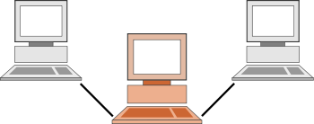
Schematic representation of a proxy server, where the computer in the middle acts as the proxy server between the other two.
In computer networks,
a proxy server is a server (a computer system or an application program) that acts as an intermediary for requests from clients seeking resources from other servers. A client connects to the proxy server, requesting some service, such as a file, connection, web page, or other resource, available from a different server. The proxy server evaluates the request according to its filtering rules. For example, it may filter traffic by IP address or protocol. If the request is validated by the filter, the proxy provides the resource by connecting to the relevant server and requesting the service on behalf of the client. A proxy server may optionally alter the client's request or the server's response, and sometimes it may serve the request without contacting the specified server. In this case, it 'caches' responses from the remote server, and returns subsequent requests for the same content directly.

A proxy server has many potential purposes, including:

  • To keep machines behind it anonymous (mainly for security).[1]
  • To speed up access to resources (using caching). Web proxies are commonly used to cache web pages from a web server.[2]
  • To apply access policy to network services or content, e.g. to block undesired sites.
  • To log / audit usage, i.e. to provide company employee Internet usage reporting.
  • To bypass security/ parental controls.
  • To scan transmitted content for malware before delivery.
  • To scan outbound content, e.g., for data leak protection.
  • To circumvent regional restrictions.

A proxy server that passes requests and replies unmodified is usually called a gateway or sometimes tunneling proxy.

A proxy server can be placed in the user's local computer or at various points between the user and the destination servers on the Internet.

A reverse proxy is (usually) an Internet-facing proxy used as a front-end to control and protect access to a server on a private network, commonly also performing tasks such as load-balancing, authentication, decryption or caching.

Saturday, January 16, 2010

Digital Signal 3

A Digital Signal 3 (DS3) is a digital signal level 3 T-carrier. It may also be referred to as a T3 line.

  • The data rate for this type of signal is 44.736 Mbit/s.
  • This level of carrier can transport 28 DS1 level signals within its payload.
  • This level of carrier can transport 672 DS0 level channels within its payload.

Cabling

DS3 interconnect cables must be made with true 75 ohm cable and connectors. Cables or connectors which are 50 ohm or which significantly deviate from 75 ohms will result in reflections which will lower the performance of the connection, possibly to the point of it not working. Bellcore standard GR-139-CORE defines type 734 and 735 cables for this application. Due to losses, there are differing distance limitations for each type of cable. 734 has a larger center conductor and insulator for lower losses for a given distance. The BNC connectors are also very important as are the crimping and cable stripping tools used to install them. Trompeter, Cannon, Amphenol, Kings, and Canare are some of the true 7.5 x 10 ohm connectors known to work. RG-6 or even inexpensive RG-59 cable will work in a pinch when properly connectorized, though it does not meet telephony technical standards.

Usage

The level of transport or circuit is mostly used between telephony carriers, both wired and wireless.

Digital Signal 0 (DS0)

Digital Signal 0 (DS0) is a basic digital signalling rate of 64 kbit/s, corresponding to the capacity of one voice-frequency-equivalent channel.[1] The DS0 rate, and its equivalents E0 and J0, form the basis for the digital multiplex transmission hierarchy in telecommunications systems used in North America, Europe, Japan, and the rest of the world, for both the early plesiochronous systems such as T-carrier and for modern synchronous systems such as SDH/SONET.

The DS0 rate was introduced to carry a single digitized voice call. For a typical phone call, the audio sound is digitized at an 8 kHz sample rate using 8-bit pulse-code modulation for each of the 8000 samples per second. This resulted in a data rate of 64 kbit/s.

Because of its fundamental role in carrying a single phone call, the DS0 rate forms the basis for the digital multiplex transmission hierarchy in telecommunications systems used in North America. To limit the number of wires required between two involved in exchanging voice calls, a system was built in which multiple DS0s are multiplexed together on higher capacity circuits. In this system, twenty-four (24) DS0s are multiplexed into a DS1 signal. Twenty-eight (28) DS1s are multiplexed into a DS3. When carried over copper wire, this is the well-known T-carrier system, with T1 and T3 corresponding to DS1 and DS3, respectively.

Besides its use for voice communications, the DS0 rate may support twenty 2.4 kbit/s channels, ten 4.8 kbit/s channels, five 9.67 kbit/s channels, one 56 kbit/s channel, or one 64 kbit/s clear channel.

E0 (standardized as ITU G.703) is the European equivalent of the North American DS0 for carrying a single voice call. However, there are some subtle differences in implementation. Voice signals are encoded for carriage over E0 according to ITU G.711. Note that when a T-carrier system is used as in North America, robbed bit signaling can mean that a DS0 channel carried over that system is not an error-free bit-stream. The out-of-band signaling used in the European E-carrier system avoids this.

software transactional memory (STM)

Software transactional memory (STM) is a concurrency control mechanism analogous to database transactions for controlling access to shared memory in concurrent computing. It functions as an alternative to lock-based synchronization. A transaction in this context is a piece of code that executes a series of reads and writes to shared memory. These reads and writes logically occur at a single instant in time; intermediate states are not visible to other (successful) transactions. The idea of providing hardware support for transactions originated in a 1986 paper and patent by Tom Knight[1]. The idea was popularized by Maurice Herlihy and J. Eliot B. Moss[2]. In 1995 Nir Shavit and Dan Touitou extended this idea to software-only transactional memory (STM)[3]. STM has recently been the focus of intense research and support for practical implementations is growing.]

Performance

Unlike the locking techniques used in most modern multithreaded applications, STM is very optimistic: a thread completes modifications to shared memory without regard for what other threads might be doing, recording every read and write that it is performing in a log. Instead of placing the onus on the writer to make sure it does not adversely affect other operations in progress, it is placed on the reader, who after completing an entire transaction verifies that other threads have not concurrently made changes to memory that it accessed in the past. This final operation, in which the changes of a transaction are validated and, if validation is successful, made permanent, is called a commit. A transaction may also abort at any time, causing all of its prior changes to be rolled back or undone. If a transaction cannot be committed due to conflicting changes, it is typically aborted and re-executed from the beginning until it succeeds.

The benefit of this optimistic approach is increased concurrency: no thread needs to wait for access to a resource, and different threads can safely and simultaneously modify disjoint parts of a data structure that would normally be protected under the same lock. Despite the overhead of retrying transactions that fail, in most realistic programs, conflicts arise rarely enough that there is an immense performance gain[citation needed] over lock-based protocols on large numbers of processors.

However, in practice STM systems also suffer a performance hit relative to fine-grained lock-based systems on small numbers of processors (1 to 4 depending on the application). This is due primarily to the overhead associated with maintaining the log and the time spent committing transactions. Even in this case performance is typically no worse than twice as slow.[4] Advocates of STM believe this penalty is justified by the conceptual benefits of STM.

Theoretically (worst case behaviour) when there are n concurrent transactions running in the same time, there could be need of O(n) memory and processor time consumption. Actual needs depends on implementation details (one can make transaction fail early enough to avoid overhead), but there will be also cases (although rare) where lock based algorithms have better theoretical computing time than software transactional memory.

Conceptual advantages and disadvantages

In addition to their performance benefits, STM greatly simplifies conceptual understanding of multithreaded programs and helps make programs more maintainable by working in harmony with existing high-level abstractions such as objects and modules. Lock-based programming has a number of well-known problems that frequently arise in practice:

  • They require thinking about overlapping operations and partial operations in distantly separated and seemingly unrelated sections of code, a task which is very difficult and error-prone for programmers.
  • They require programmers to adopt a locking policy to prevent deadlock, livelock, and other failures to make progress. Such policies are often informally enforced and fallible, and when these issues arise they are insidiously difficult to reproduce and debug.
  • They can lead to priority inversion, a phenomenon where a high-priority thread is forced to wait on a low-priority thread holding exclusive access to a resource that it needs.

In contrast, the concept of a memory transaction is much simpler, because each transaction can be viewed in isolation as a single-threaded computation. Deadlock and livelock are either prevented entirely or handled by an external transaction manager; the programmer need hardly worry about it. Priority inversion can still be an issue, but high-priority transactions can abort conflicting lower priority transactions that have not already committed.

On the other hand, the need to abort failed transactions also places limitations on the behavior of transactions: they cannot perform any operation that cannot be undone, including most I/O. Such limitations are typically overcome in practice by creating buffers that queue up the irreversible operations and perform them at a later time outside of any transaction. In Haskell, this limitation is enforced at compile time by the type system.

ATM(Asynchronous Transfer Mode)

(ATM) is a standardized digital data transmission technology. ATM is implemented as a network protocol and was first developed in the mid 1980s.[1] The goal was to design a single networking strategy that could transport real-time video conference and audio as well as image files, text and email.[2] The International Telecommunications Union, American National Standards Institute, European Telecommunications Standards Institute, ATM Forum, Internet Engineering Task Force, Frame Relay Forum and SMDS Interest Group were involved in the creation of the standard.[3]

Asynchronous Transfer Mode is a cell-based switching technique that uses asynchronous time division multiplexing.[4][5] It encodes data into small fixed-sized cells (cell relay) and provides data link layer services that run over OSI Layer 1 physical links. This differs from other technologies based on packet-switched networks (such as the Internet Protocol or Ethernet), in which variable sized packets (known as frames when referencing Layer 2) are used. ATM exposes properties from both circuit switched and small packet switched networking, making it suitable for wide area data networking as well as real-time media transport.[6] ATM uses a connection-oriented model and establishes a virtual circuit between two endpoints before the actual data exchange begins.[7]

ATM is a core protocol used over the SONET/SDH backbone of the Integrated Services Digital Network.

ATM has proven very successful in the WAN scenario and numerous telecommunication providers have implemented ATM in their wide-area network cores. Many ADSL implementations also use ATM. However, ATM has failed to gain wide use as a LAN technology, and lack of development has held back its full deployment as the single integrating network technology in the way that its inventors originally intended. Since there will always be both brand-new and obsolescent link-layer technologies, particularly in the LAN area, not all of them will fit neatly into the synchronous optical networking model for which ATM was designed. Therefore, a protocol is needed to provide a unifying layer over both ATM and non-ATM link layers, as ATM itself cannot fill that role. IP already does that; therefore, there is often no point in implementing ATM at the network layer.

In addition, the need for cells to reduce jitter has declined as transport speeds increased (see below), and improvements in Voice over IP (VoIP) have made the integration of speech and data possible at the IP layer, again removing the incentive for ubiquitous deployment of ATM. Most Telcos now plan to integrate their voice network activities into their IP networks, rather than their IP networks into the voice infrastructure.

MPLS, a generic Layer 2 packet-switching protocol, adopted many technically sound ideas from ATM. ATM remains widely deployed, and is used as a multiplexing service in DSL networks, where its compromises fit DSL's low-data-rate needs well. In turn, DSL networks support IP (and IP services such as VoIP) via PPP over ATM and Ethernet over ATM (RFC 2684).

ATM will remain deployed for some time in higher-speed interconnects where carriers have already committed themselves to existing ATM deployments; ATM is used here as a way of unifying PDH/SDH traffic and packet-switched traffic under a single infrastructure.
It is often claimed that "ATM is increasingly challenged by speed and traffic shaping requirements of converged networks. In particular, the complexity of Segmentation and Reassembly (SAR) imposes a performance bottleneck, as the fastest SARs known run at 10 Gbit/s". However with ATM interfaces available at up to STM-16 (2.5Gbps - such as the Cisco SPA-1XOC48-ATM for their 7600 series routers) and even STM-64 (10Gbps for example the Cisco MGX 8950 OC-192c/STM-64) ATM can still readily challenge even 10GE interfaces for speed and typically exceed the ability of other protocols in terms of Quality of Service - especially on busy links.

As far as SAR issues are concerned, since SAR is carried out at the edge of an ATM network, this is not a core switching issue but rather a task left to the edge devices (or the applications themselves) and currently (as at 2009) it would be true to say that any single interface on a Router is struggling to exceed 10Gbps throughput and this 10Gbps limitation is not limited to merely ATM SAR but also the switching and routing capabilities of Router interfaces in general.

Currently, it seems likely that gigabit Ethernet implementations (10Gbit-Ethernet, Metro Ethernet) will replace ATM as a technology of choice in new WAN implementations.

Interest in using native ATM for carrying live video and audio has increased recently. In these environments, low latency and very high quality of service are required to handle linear audio and video streams. Towards this goal standards are being developed such as AES47 (IEC 62365), which provides a standard for professional uncompressed audio transport over ATM. This is worth comparing with professional video over IP.

Tuesday, January 5, 2010

Firewall

Firewall

An illustration of how a firewall works.
A firewall is a part of a computer system or network that is designed to block

rt of a computer system or network that is designed to block unauthorized access while permitting authorized communications. It is a device or set of devices configured to permit, deny, encrypt, decrypt, or proxy all (in and out) computer traffic between different security domains based upon a set of rules and other criteria.

Firewalls can be implemented in either hardware or software, or a combination of both. Firewalls are frequently used to prevent unauthorized Internet users from accessing private networks connected to the Internet, especially intranets. All messages entering or leaving the intranet pass through the firewall, which examines each message and blocks those that do not meet the specified security criteria.

There are several types of firewall techniques:

  1. Packet filter: Packet filtering inspects each packet passing through the network and accepts or rejects it based on user-defined rules. Although difficult to configure, it is fairly effective and mostly transparent to its users. In addition, it is susceptible to IP spoofing.
  2. Application gateway: Applies security mechanisms to specific applications, such as FTP and Telnet servers. This is very effective, but can impose a performance degradation.
  3. Circuit-level gateway: Applies security mechanisms when a TCP or UDP connection is established. Once the connection has been made, packets can flow between the hosts without further checking.
  4. Proxy server: Intercepts all messages entering and leaving the network. The proxy server effectively hides the true network addresses.